Photovoltaic systems
Volker Quaschning describes the basics of direct solar electricity generation using photovoltaic systems, looking at the different cell and module types and the related technology.
The history of photovoltaics goes back to the year 1839, when Becquerel discovered the photovoltaic effect, but no technology was available in the 19th century to exploit this discovery. The semiconductor age only began about 100 years later. After Shockley had developed a model for the pn junction, Bell Laboratories produced the first solar cell in 1954; the efficiency of this, in converting light into electricity, was about 5 %.
Principle of Solar Cells
Electrons and the ‘holes’ they leave behind are, respectively, negative and positive charge carriers, which usually appear in pairs within solid matter. Semiconductors are used to produce solar cells, and the characteristics of the semiconductor material make it easy for incoming photons of sunlight to release electrons from the electron hole binding. Leaving the holes behind them, the released electrons can move freely within the solid.
However, these movements have no clear direction; to make use of the
electricity, it is necessary to collect electrons. The semiconductor material is
therefore polluted with ‘impure’ atoms. Two different kinds of atom produce an
n-type and a p-type region inside the semiconductor, and these two
neighbouring regions generate an electrical field (see Figure 1). This field can
then collect electrons, and draws free electrons released by the photons to the
n-type region. The holes move in the opposite direction, into the p-type region.
However, not all of the energy from the sunlight can generate free electrons. There
are several reasons for this. Part of the sunlight is reflected at the surface of the
solar cell, or passes through the cell. In some cases, electrons and holes
recombine before arriving at the n-type and p-type regions (figure 1 shows these processes in a
photovoltaic (PV) cell.). Furthermore, if the
energy of the photon is too low – which is the case with light at long wavelengths,
such as infrared – it is not sufficient to release the electron. On the other hand, if
the photon energy is too high, only a part of its energy is needed to release the
electron, and the rest converts to heat.
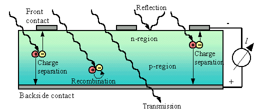
FIGURE 1. Processes occurring in an irradiated PV cell
The model shown in Figure 2 provides a figurative demonstration of the way in
which a solar cell works. The model consists of two flat levels; the first level
has plenty of holes, and these are filled with water. Rubber balls then fall onto this
level, and water splashes from the holes. Although some water splashes back onto
the first level, some reaches the second level; it flows from there to a waterwheel
that drives a dynamo and generates electricity. On the first level, water flows
back into the holes, to be hit again by further rubber balls. In this model the
rubber balls represent the photons of sunlight, the two levels are the n-type and
p-type regions, and the water signifies the electrons.
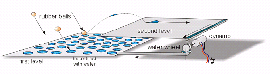
FIGURE 2. Modelling the principle of solar cell operation
Solar Cell Materials
Various semiconductor materials are suitable for solar cell production; however, silicon is the most frequently used material today, being employed in the manufacture in the majority of solar cells. The second most common chemical element in the earth’s crust (after oxygen), silicon can mainly be found in quartz sand (SiO2). A reduction process is used to extract silicon from the quartz sand at high temperatures, and the next step is to remove remaining impurities from the polycrystalline silicon. Polycrystalline silicon crystals are oriented in different ways, separated by grain boundaries, which introduces some efficiency losses. Seeding a single crystal at high temperatures can transform the polycrystalline silicon into monocrystalline silicon, and, with no grain boundaries present in the resulting material, losses within a solar cell are thus reduced. However, more energy is needed to produce monocrystalline silicon, and it is more expensive.
Besides crystalline silicon, thin-film modules present promise as a future solution. These can be made of amorphous silicon and other materials such as cadmium telluride (CdTe) or copper indium diselenide (CuInSe2, or CIS). Thin-film modules can be produced using only a fraction of the semiconductor material necessary for crystalline cells, and their development potential is therefore very high. However, it is not yet clear which material will dominate future markets. Most experts say that crystalline solar cells will continue to dominate for the rest of this decade, but thereafter, other materials could become more important, provided they can be produced more economically.>
Solar Cell Parameters
Most photovoltaic data sheets present a lot of parameters; the most common terms relating to crystalline solar cells will be explained here.
The solar cell generates a current, and this current varies with the cell voltage. Current–voltage characteristics usually show this correlation. When the voltage of this solar cell is zero – described as a ‘short-circuited’ solar cell – the ‘short circuit current’ ISC, proportional to irradiance on the solar cell, can be measured. The ISC rises with increasing temperature, though the standard temperature for reporting short circuit currents is usually 25 °C. If the cell current is equal to zero, the solar cell is described as ‘open-circuited’. The cell voltage then becomes the ‘open circuit voltage’, VOC. The dependence of VOC on the irradiance is logarithmic. At the same time VOC decreases at a faster rate with rising temperature than the ISC increases. Therefore, the solar cell’s maximum power and the cell efficiency decrease with rising temperature. For most cells, a temperature rise of 25 °C causes a power drop of about 10 %.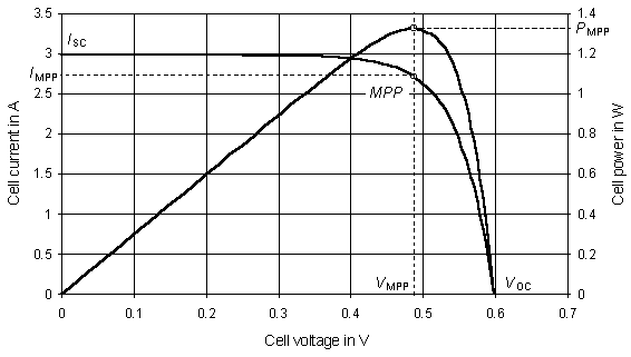
FIGURE 3. Current–voltage and power–voltage solar cell characteristics, showing MPP
The solar cell generates its maximum power at a certain voltage. Figure 3 shows the current–voltage and power–voltage characteristics. It shows clearly that the power curve has a point of maximum power, called, quite straightforwardly, the ‘maximum power point’, MPP. The maximum power point voltage, VMPP, is less than the open circuit voltage, and the current IMPP is lower than the short circuit current. At the MPP, current and voltage have neraly the same relation to irradiance and temperature as the short circuit current and open circuit voltage.
In order to make solar cells and modules comparable, MPP power is
measured under standard test conditions (STC): irradiance at 1000 W/m2, a
temperature of 25 °C, and air mass (AM) 1.5. The power generated by the solar
modules in real weather conditions is usually lower, hence STC power has the
unit Wp (Watt peak). In terms of dependence on irradiance, the current
dominates the device’s behaviour, so that the MPP power is nearly proportional to
the irradiance.
Solar cell efficiency is the ratio of the maximum electrical solar cell power to the
radiant power on the solar cell area. Saleable crystalline solar cells now reach
efficiencies up to almost 20 %, but in the laboratory, efficiencies of more than 25 %
are possible. The efficiencies of thin-film solar cells are, however, lower.
Production of Solar Modules
Solar cells are not normally operated on an individual basis, due to their low voltage, and in PV modules, cells are mostly connected in series. Single, unprotected crystalline silicon solar cells can also be damaged rapidly, due to climatic influences, so to avoid this, several crystalline cells of edge length 10–15 cm (4–6 inches) are combined in the form of a solar module for protection. The front cover of this is formed by glass with a low iron content, and the back cover consists of glass or plastic. Between the front and back covers, the solar cells are embedded within plastic, usually EVA (ethylene vinyl acetate), which is cured at temperatures of 100 °C. This process is called lamination. A frame is in some cases added to the finished modules, while a junction box is used to protect the contacts from water, and to mount bypass diodes inside.
If just one cell of a large number of series-connected cells becomes shaded, then the shaded cell starts blocking the current, and the whole string then stops generating power. The bypass diode cannot avoid the disproportionate power loss, but can avoid possible damage to the shaded cells. However, partial shading of PV generators should be avoided whenever possible.
The base for thin-film modules is a substrate. In most cases, this is made of glass or a metal foil, and spray and deposition processes then add the solar cell materials and cell contacts. The solar cells are interconnected directly in series within the module. Finally, the samples are then either laminated or coated with a polymer, to protect the solar module from climatic influences.
Stand-alone Systems
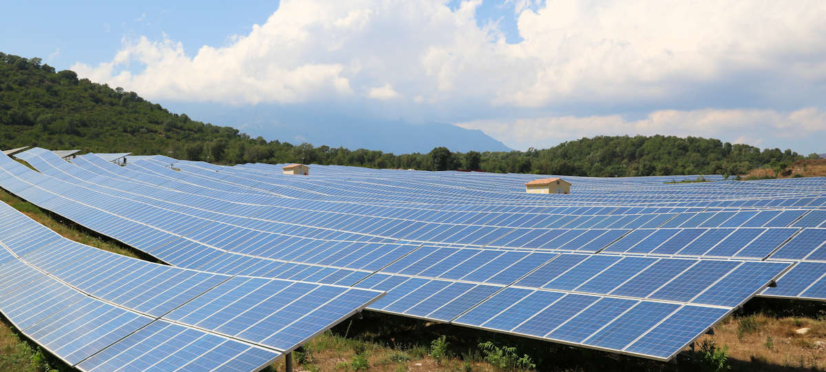
Connection of PV modules in series, parallel or series–parallel combinations builds up the solar generator (as is shown in the photograph below left). Consumers are hardly ever connected directly to the solar generator, however, as in reality photovoltaic systems are more complex. In the absence of any kind of storage, there will be periods without any power for a system solely powered by photovoltaics, which is clearly not desirable.
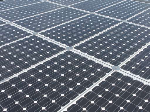
PV modules connected in parallel and series build up the PV generator
Today, the most common method for electricity storage is the lead–acid battery, and the main reason for this is cost. The car industry in particular prefers lead batteries. So-called ‘solar batteries’ have a slightly modified structure, compared with car batteries, in order to achieve longer lifetimes. The simplest battery system consists only of a PV generator, a battery and the load. Rechargeable batteries in simple battery systems, with the PV generator and load directly connected to the battery, are not, however, protected against deep discharge or overcharging. Therefore, such systems should only be chosen if negative operating conditions can definitely be avoided – otherwise, the battery can be damaged very quickly. As a consequence, most battery systems use a charge controller; today, most of these are parallel charge controllers, as seen in Figure 4. This charge controller measures the battery voltage and disconnects the load if the battery is nearly empty; if the battery is full, the PV generator is shortcircuited, and in this case a blocking diode avoids battery discharge. An inverter can be also added to the battery system to drive alternating current (AC) loads.
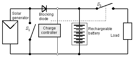
FIGURE 4. PV battery system with parallel charge controller
Grid-connected Systems
A large number of photovoltaic systems installed in industrial nations today are grid-connected. An inverter converts the direct current (DC) voltage of the modules to the two-phase or three-phase AC voltage of the public grid. The inverter usually has an integrated MPP tracker which operates the PV generator at the maximum power point. However, the voltage and current generated by the PV modules must fit within the inverter range. If PV modules are connected in series, their voltage is added to give the total voltage, whereas the current of parallel PV modules is added to give the total current.
Photovoltaic inverters only operate at rated power for a very few hours in any year, as, due to changes in solar irradiance, they work predominantly at part load. Therefore, it is very important that inverters have high efficiencies, even when operating at these part loads. A representative efficiency is used to compare different inverters, the so-called ‘Euro efficiency’. This is clearer than the term ‘average efficiency’, and is the average efficiency for typical European irradiance conditions.
There are several different inverter concepts that can be used when setting up a PV system. As Figure 5 demonstrates, these are:
- a number of parallel PV module strings connected to central inverters, which can convert the PV generator power up to several hundred kilowatts
- only one PV string, with a power range between 500 W and 2.5 kW, connected to a string inverter
- module inverters, used to connect a single module to the grid; these operate well even if some modules are shaded or do not have exactly the same power, though general inverter efficiencies decrease with smaller systems.
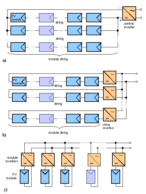
FIGURE 5. Connection of photovoltaic modules to inverters using a) central inverter; b) string inverter; c) module inverter
Market and Environment
One argument often used against photovoltaics is the huge amount of energy needed to produce PV systems, with the idea that more energy is used to produce systems than they can generate in their lifetime. However, a multitude of studies has proven that the energy balance of PV systems is clearly positive – today’s systems need between two and five years to pay back the energy used in production, depending mainly on annual solar irradiation. Future thin-film systems with lower material needs will reduce this period significantly, and recycling of photovoltaic modules is also possible. The lifetime of today’s PV modules is expected to be 25–30 years, and some module manufacturers give 25-year warranties.
In 2002, more than 1900 MW of photovoltaics were installed worldwide. Japan has the highest installed capacity, followed by Germany and the US; between them, these three countries represent about two thirds of global PV capacity. Market growth rates in the last 10 years were between 20 % and 40 % per year, and in recent decades, there was a price reduction of 20 % when the market volume doubled. As a result of this, photovoltaic prices dropped by 50 % or more every decade.
It is not sure how long this price reduction process will continue. However, photovoltaics has the potential to become competitive even with conventional gridconnected systems, in a few decades. The potential for PV is huge, and in theory, PV could meet the total global electricity demand. Along with the other renewables, it is one of the most important options for a future, climate-compatible electricity supply.